


August 29, 2026 Structured Light and the Stitched Mesh: How an Intraoral Scanner Turns Projected Patterns Into a 3D Model
Watch a clinician sweep a wand across an arch and a full-color model blooms onto the screen in seconds, apparently in a single continuous gesture. It is one of the most convincing illusions in modern dentistry – because a digital impression is not captured the way a photograph is. It is assembled. The wand does not take one picture of the mouth; it takes thousands of tiny optical measurements and knits them, in real time, into a single surface. To understand where an intraoral scanner excels and where it quietly struggles, it helps to stop admiring the finished mesh and look instead at how each fragment of it was measured in the first place.
The Problem: Reading Depth From a Flat Sensor
Every camera sensor is fundamentally two-dimensional. It records how much light lands on a grid of pixels; it does not, on its own, know how far away any of that light originated. A photograph of a tooth flattens a curved, glossy, three-dimensional object into a plane, and the depth is inferred by our eyes from shading and familiarity. An intraoral scanner cannot afford to infer. It has to measure depth – a real distance, in microns, for point after point across the surface – and it has to do so through saliva, into shadowed interproximal spaces, on a substrate that is translucent and specular rather than the matte, cooperative surface any optical engineer would prefer. The two dominant ways scanners solve this problem are structured light and confocal sensing, and the choice shapes the character of everything downstream.
Structured Light: Measuring the Bend in a Pattern
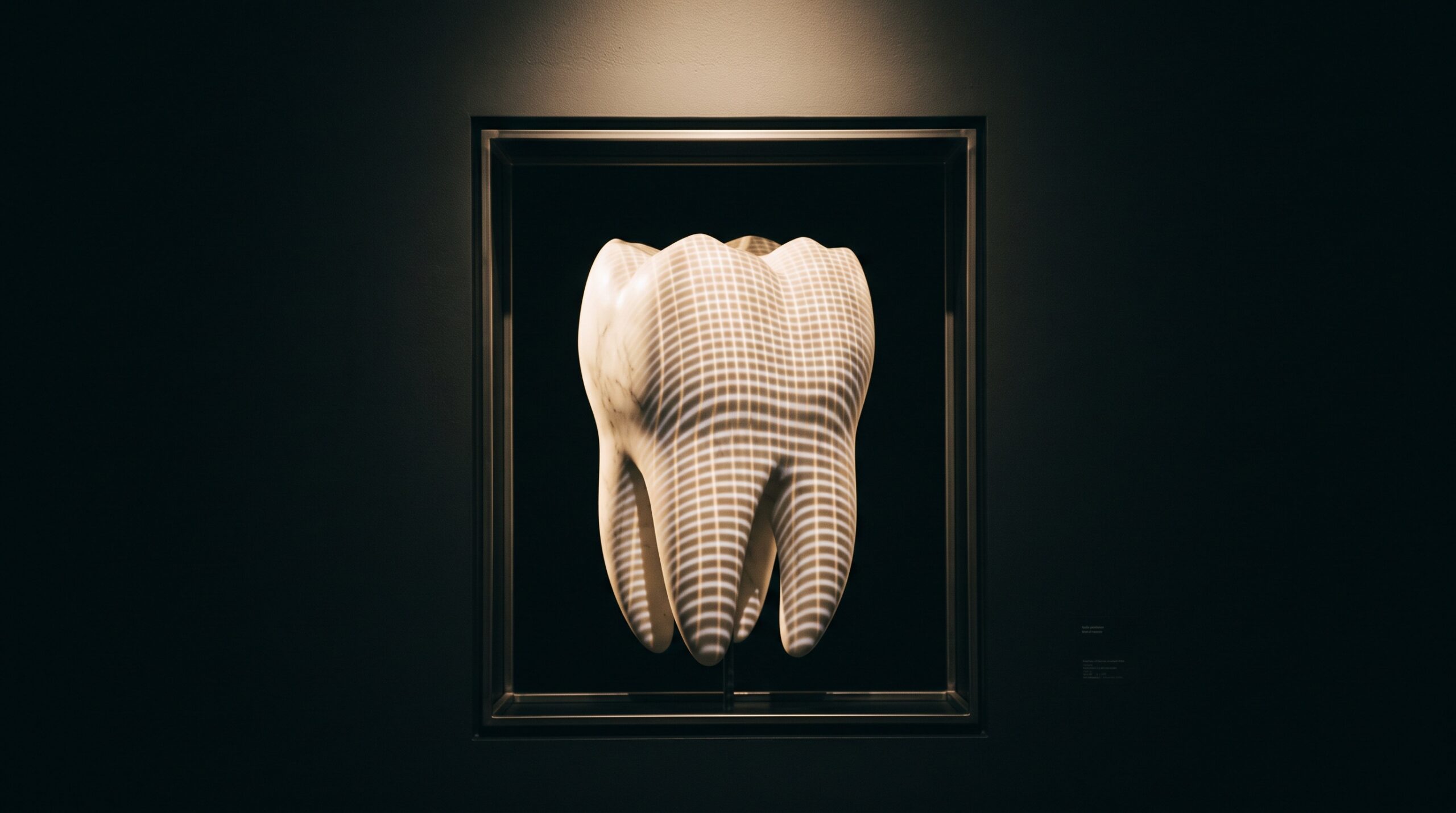
The first approach turns the sensor’s blindness to depth into a geometry problem it can solve. Rather than photographing the tooth under plain illumination, the scanner projects a known pattern onto it – a grid, a set of parallel stripes, or a fine sinusoidal fringe. A second camera, mounted at a fixed, deliberate angle to the projector, watches how that pattern lands. On a flat surface the stripes would stay straight and evenly spaced. On the ridges and grooves of a real tooth they bend, crowd together, and shift. Because the geometry of the projector, the camera, and the angle between them is known precisely, the displacement of each stripe can be converted, by triangulation, into a distance. The pattern is a ruler made of light, and the surface is measured by how much it distorts that ruler.
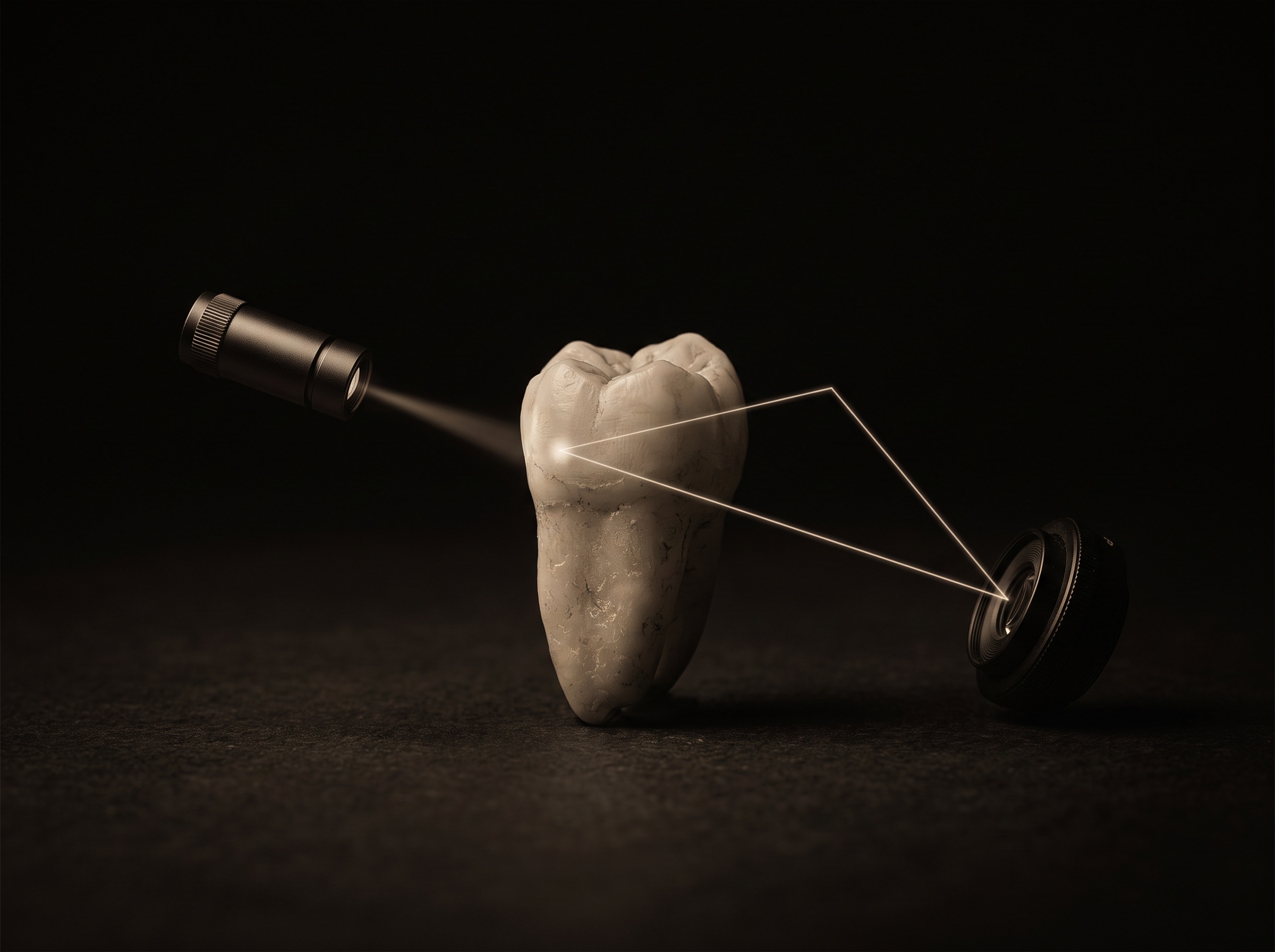
Triangulation is the quiet workhorse here: projector, a point on the tooth, and camera form a triangle, and solving that triangle for one unknown side gives the depth of the point. Do this for every illuminated point in a single frame and you recover not one distance but a dense field of them – a small 3D patch of surface captured in a single instant. It is the same family of physics behind close-range photogrammetry, where multiple views of fixed reference points reconstruct a shape; structured light simply supplies its own reference pattern rather than hunting for natural features.
Confocal Sensing: Measuring Depth by Focus
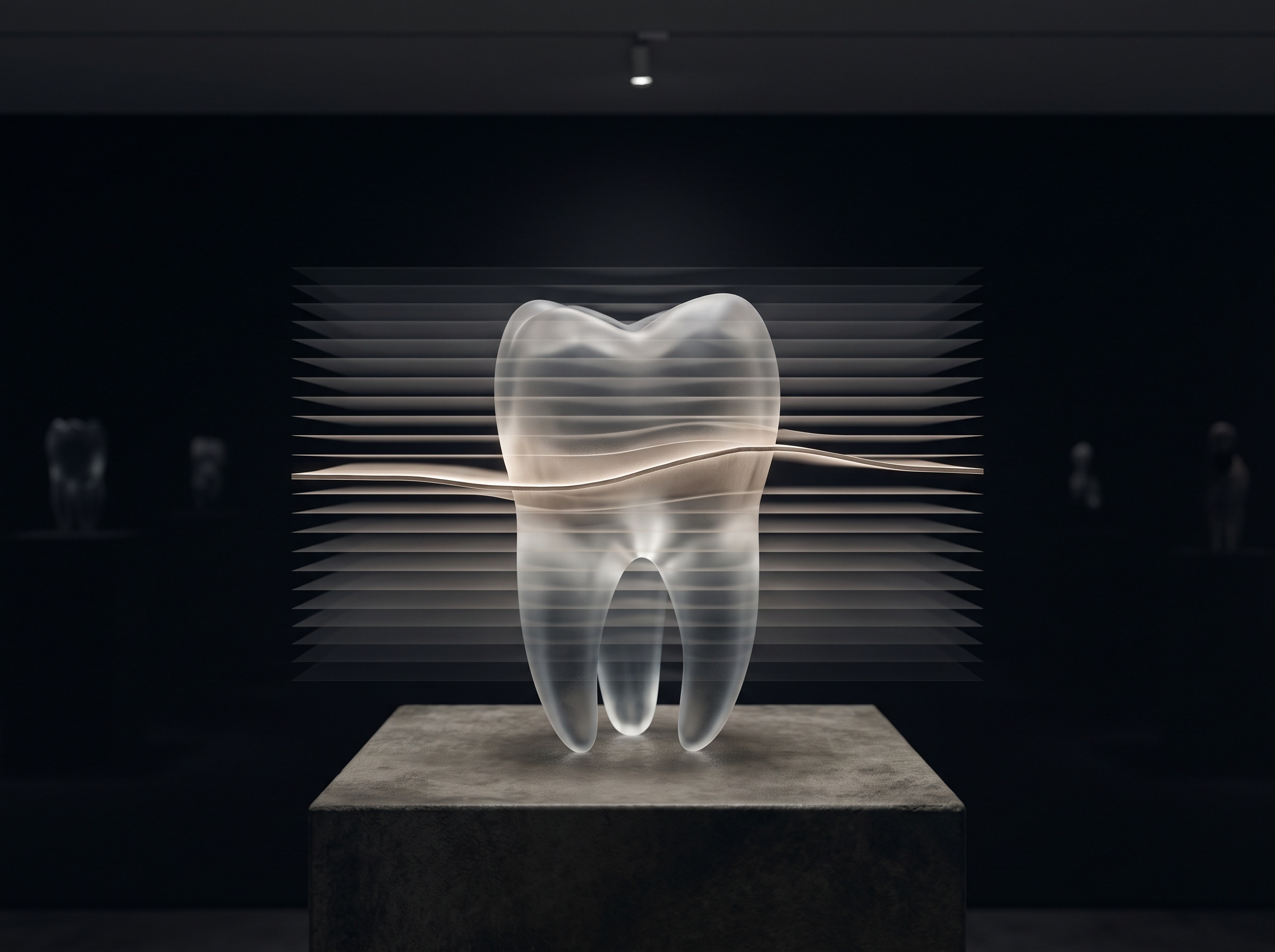
The second major approach discards triangulation entirely and measures depth through focus. In a confocal optical system, light returning from the mouth passes back through a pinhole aperture before it reaches the detector, and that pinhole is unforgiving: only light originating from one precise focal depth passes cleanly through and registers sharply. Light from any other depth is rejected as blur. On its own that would sample only a single thin plane, so the scanner rapidly sweeps its focal plane through a range of depths, and for each point on the surface it notes the exact focal setting at which that point snapped into sharpest focus. The depth that produced maximum sharpness is the depth of the surface. Where structured light asks “how far has the pattern shifted,” a confocal system asks “at what focus does this point become crisp” – and answers in microns.
Each method has a temperament. Triangulation systems are fast and information-dense per frame but can be foiled where the angled camera cannot see the point the projector lit – deep, narrow interproximal valleys and steep subgingival walls. Confocal systems tolerate some of those geometries gracefully and are relatively forgiving of the wet, glossy enamel that scatters a projected pattern, which is part of why several modern scanners abandoned the reflective-powder step that older devices required. Neither is universally superior; both are engineering answers to the same stubborn question of extracting real depth from returning light.
From Patches to a Mesh: The Stitch Is the Scan
Whichever method captures a frame, one frame is never enough. Each measurement yields only a small patch of surface – the sliver the wand happened to be over at that instant – and it arrives as a point cloud, a dense scatter of 3D coordinates with no connective tissue between them. The magic that looks like a continuous scan is really registration: as the wand moves, each new patch overlaps the previous one, and the software solves for the rigid rotation and translation that best aligns the shared region, typically with an iterative-closest-point style optimization that nudges the new patch until its overlap with the growing model is as tight as possible. Frame after frame is snapped into a common coordinate system, and only once the points are aligned are they woven into a triangulated mesh – the continuous surface that ultimately exports as an STL for a mill or printer.
This is the pivotal fact for anyone who cares about accuracy: the model is a chain of registrations, and a chain is only as trustworthy as its weakest link. A small alignment error in one frame does not simply average out – it propagates, tilting every patch that registers to it afterward. Over a single tooth or a quadrant the error stays negligible. Over a full arch, a long unbroken span of featureless palate or edentulous ridge starves the algorithm of the overlapping detail it needs to lock onto, and the accumulated drift can bow the far end of the arch by a clinically meaningful amount. This is precisely the distinction our piece on trueness versus precision dwells on: a scanner can be exquisitely repeatable and still drift away from the true anatomy as the span grows, because repeatable stitching errors are still errors.
Why the Capture Principle Governs the Craft
Understanding the acquisition explains the scanning strategies clinicians are taught almost as folklore – keep the wand close and moving smoothly, do not sweep too fast, follow a consistent path, and give the algorithm feature-rich landmarks to hold onto rather than gliding across a smooth expanse. None of that is superstition; it is direct accommodation of how depth is measured and how patches are stitched. It also explains why a clean digital impression is a genuine act of craft rather than a button press, and why the resulting model behaves so well when it is later combined with other data – the surface a scanner produces is what gets aligned to the radiographic volume in multimodal fusion, and a mesh that drifted during capture carries that drift into every downstream use.
Future Developments
The trajectory of optical impressioning is toward capture that forgives the mouth rather than fighting it: wider fields of view that gather more overlap per frame and shorten the registration chain, faster focal sweeps and pattern projection that tolerate motion and moisture, and increasingly capable software that recognizes anatomy well enough to close the drift over a long arch instead of merely minimizing local misalignment. Color and translucency data are being folded into the same pass, so the scan begins to carry not just shape but the material character of the surface. Yet the underlying grammar is unlikely to change: a flat sensor, a clever way to make it report depth, and the patient discipline of stitching a thousand small truths into one continuous whole. The intraoral scan has quietly become one of the most sophisticated imaging acts performed chairside – a model that looks captured in an instant but is, in truth, composed frame by frame, like a mosaic assembled faster than the eye can follow.
Sorry, the comment form is closed at this time.