


August 14, 2026 The Anode Heel Effect: The Invisible Gradient Shading Every Radiograph
Look closely at a large radiograph and you may notice something the anatomy alone cannot explain: one edge of the field sits a shade denser than the other, a smooth wash of exposure fading gently across the image as though a light had been held slightly off-centre. It is tempting to blame positioning, or processing, or the patient’s own asymmetry. But the gradient is often older than any of those — it is present in the beam before it leaves the tube, stitched into the geometry of how X-rays are made. This is the anode heel effect, one of the oldest and most elegant quirks in radiographic physics, and understanding it turns an apparent flaw in the image into something a careful operator can read, predict, and even exploit.
Where the Gradient Is Born
An X-ray tube does not make its photons at a surface; it makes them at a depth. A fine ribbon of electrons boils off the filament, accelerates across the tube, and slams into the tungsten anode, and the X-rays that result are generated not at the very face of the metal but within it, a fraction of a millimetre below where the electrons come to rest. To escape and become a useful beam, each photon must then travel back out through the target material itself. And here the geometry of the anode matters enormously: the target is not flat to the beam but steeply angled, a design borrowed from the line-focus principle that lets a broad electron footprint present as a small, sharp focal spot. That same clever angle means the metal a photon must traverse on its way out depends on the direction it happens to be heading.

The Cathode Side Runs Brighter
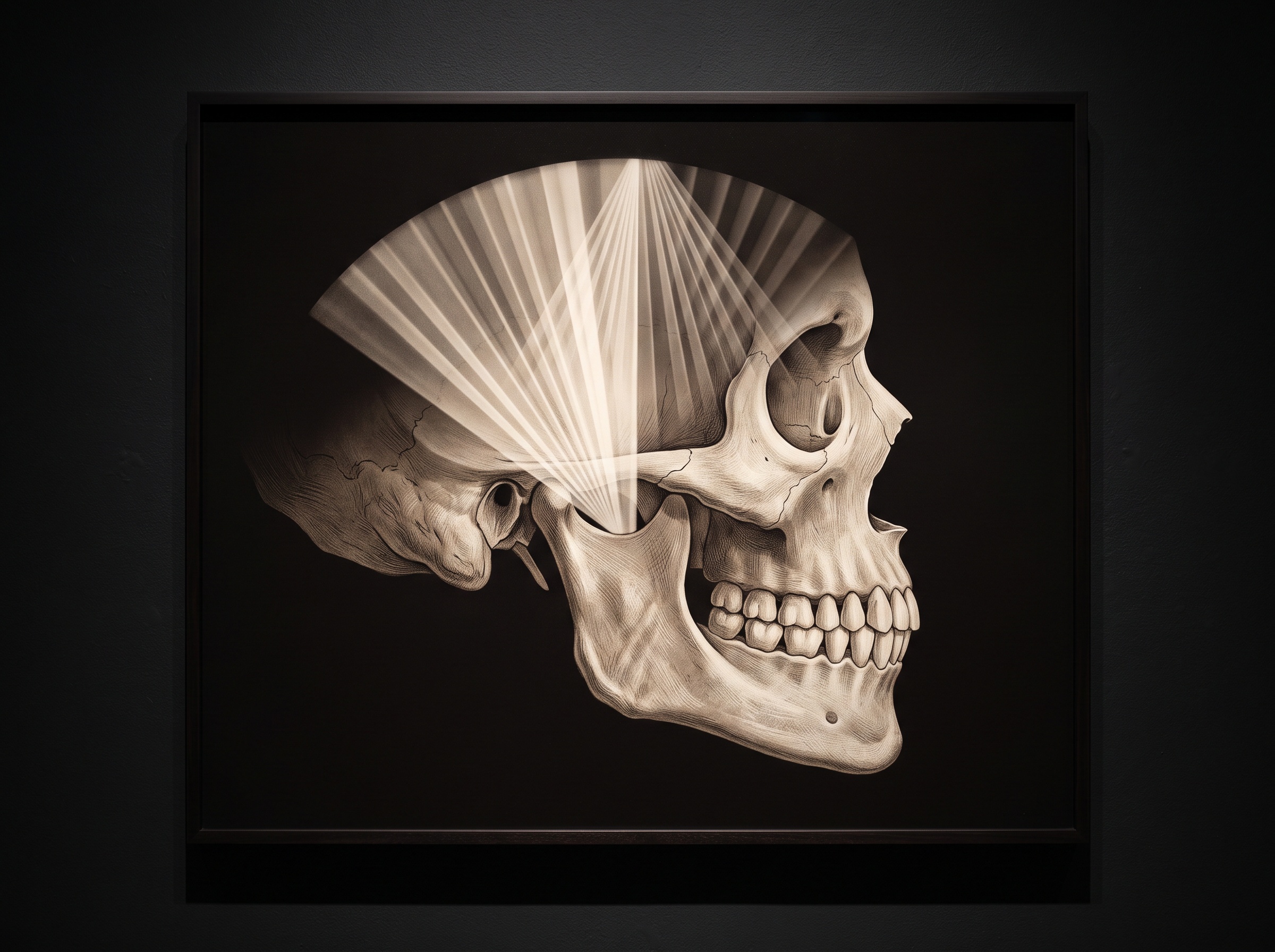
Consider two photons born at the same point in the target. One is aimed toward the cathode end of the tube; it exits through a shallow sliver of tungsten and emerges strong. The other is aimed toward the anode end; because of the target’s angle, it must climb out through a much longer path of dense metal, and a good fraction of its fellows are absorbed along the way. The net result, integrated across the whole beam, is an intensity that is measurably higher on the cathode side of the field and tapers toward the anode side — the “heel” of the anode casting its long, soft shadow over half the image. The difference is not trivial; across a wide field it can amount to a substantial swing in the number of photons reaching one edge versus the other, and that swing prints directly as a difference in radiographic density. This is a variation in the sheer quantity of the exposure, which is why it reads as density rather than contrast — a distinction explored in the grayscale craft of density and contrast.
What Sharpens the Effect — and What Hides It
Three variables govern how visible the heel effect becomes, and all three are geometric. The first is the anode angle: the steeper the target, the longer the self-absorption path on the anode side and the more pronounced the gradient. The second is field size. A narrow beam samples only the flat central plateau of the intensity distribution, where the falloff is gentle; open the collimation to a wide field and you capture the beam’s steep shoulders, where the imbalance is unmistakable. The third is the source-to-image distance. Move the receptor closer to the tube and the beam diverges more steeply across it, exaggerating the gradient; pull it farther away and the same physical field subtends a smaller angular slice of the beam, flattening the effect. These are the same levers of geometry and divergence that quietly set the ceiling on how sharp a dental image can truly be — proof, again, that the character of a radiograph is decided long before the anatomy enters the frame.

The Dental Reality: Small Fields, Subtle Shadows
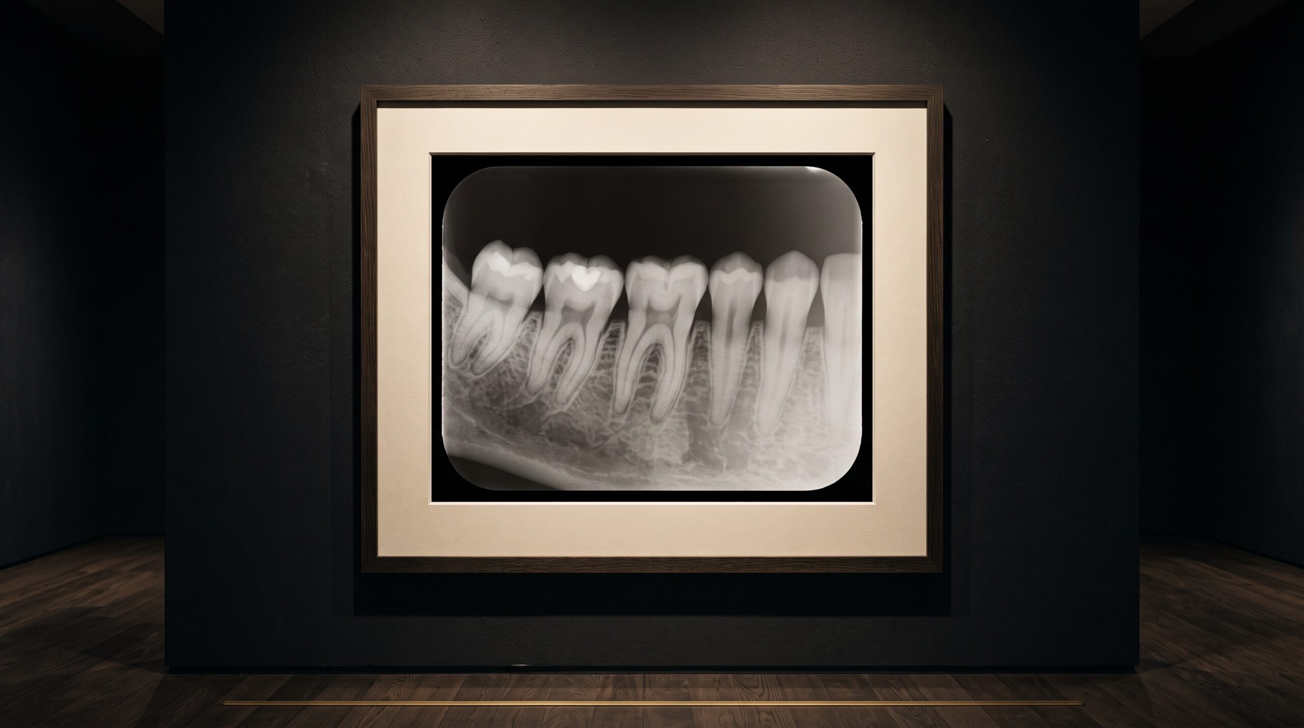
For a single intraoral exposure, the honest answer is that the heel effect is nearly invisible. The field is small, the collimated beam samples only the beam’s even centre, and the distances are short and standardised; whatever gradient exists is buried beneath the ordinary variations of anatomy and technique. Where the effect steps out of the shadows is in the large-field modalities. Panoramic and cephalometric imaging spread a wide, divergent beam across a broad receptor, and there the intensity distribution of the source can express itself as a genuine, visible slope in density from one side of the film or sensor to the other. It is one of several ways in which the machine’s own construction, rather than the patient, writes itself onto the picture — a cousin of the projection and reconstruction signatures catalogued when reading a bitewing or a panoramic, where the honest reader learns to separate what the anatomy shows from what the geometry imposes. Even a perfectly efficient detector, one with excellent detective quantum efficiency, faithfully records this gradient, because the imbalance is in the photons it is handed, not in the sensor that receives them.

Turning the Flaw Into a Tool
The most satisfying part of the story is that the heel effect need not be merely tolerated; it can be recruited. Because the beam is inherently brighter on the cathode side and dimmer on the anode side, an operator who knows which end of the tube is which can orient the patient so that the thickest, densest anatomy sits under the cathode’s stronger flux and the thinnest anatomy under the gentler anode side. The extra photons compensate for the extra tissue, and the gradient that would otherwise blemish the image instead flattens the exposure into something more uniform than a perfectly even beam would produce. It is a small, classical piece of craft — the kind of quiet, geometry-aware decision that separates a merely adequate radiograph from a considered one. The flaw, understood well enough, becomes a form of built-in compensation.
Future Developments
Modern hardware is steadily softening the heel effect’s grip. Beam-shaping filters, bow-tie and wedge compensators, and careful collimation can pre-equalise the field before it reaches the patient, and in fully digital workflows a flat-field calibration — imaging a uniform target and recording the beam’s own gradient — lets the software subtract the heel’s signature from every subsequent exposure. As CBCT and flat-panel systems mature, that per-pixel gain correction quietly erases much of what was once an unavoidable slope in density. Yet the physics beneath it does not go away; it is merely accounted for. And there is a certain elegance in that continuity: a hundred and thirty years after the first tubes, the same angled sliver of tungsten that lets us focus the beam still tilts its intensity across the field, and the art of imaging remains, in part, the art of knowing precisely how the instrument shades its own truth — and correcting for it with open eyes.
Sources & further reading:
Sorry, the comment form is closed at this time.